 |

|
 |


Begin OCR Text:
P 1 8OO
H O R N S
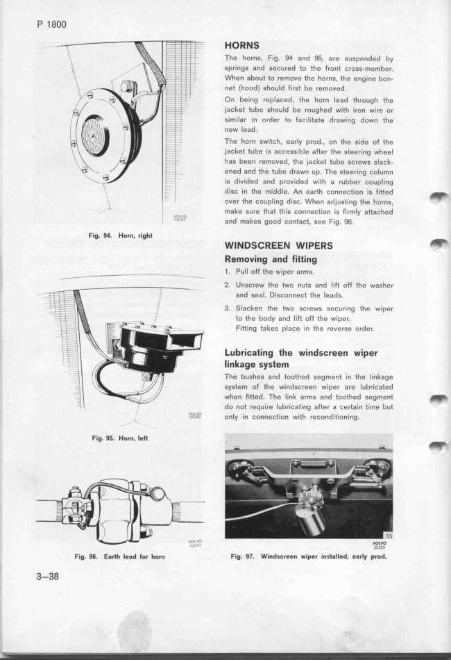
The forns, Fig. 94 and 95, are suspended by
springs and secured to the front cross-member.
When about to remove the horns, the engine bon-
net (hood) should fi rst be removed.
On being replaced, the horn lead through the
jacket tube shou Id be roughed with iron wi re or
sim ilar in order to facilitate drawing down the
new lead.
The horn switch, early prod., on the side of the
jacket tube is accessible after the steering wheel
has been removed, the jacket tube screws slack-
ened and the tube drawn up. The steering column
is d ivided and provided with a rubber coupling
d isc in the middle. _n earth connection is fitted _
over the coupl ing disc. When adjusting the f.orns,
,,,, v,, make sure that this connection is fi rm_y attached
'''''_ and makes good contact, see Fig. 96.
Fig. 94. Horn, right w_ N DS_ff EE N w_peffS _
Removing and fitting
__ - - 1 . Pul l off the wiper arms.
-_ 2. Unscrew the two nuts and lift off the washer
;, _i... and sea_. Disconnect tfe _eads.
'; _ 3. Slacken the two screws securing the wiper
to the body and lìft off the wiper.
Fitting takes place in the reverse order.
Lubri_ating the winds_reen wíper
linkage system
The bushes and toothed segment in the linkage
system of the windscreen wiper are lubricated
when fitted. __he Iink arms and toothed segment _
do not require lubricating after a certain time but
'iO_i'i'_?i on Iy in connection with reconditioning.
Fig. 9f. Horn. Ie_ . _
_ '
VO_VO
__ _3233
Fig. 96. E8rtf lead for horn Fig. 97. Windscreen wiper installed, early prod.
3-38
|

