 |

|
 |


Begin OCR Text:
/
P 1 8OO
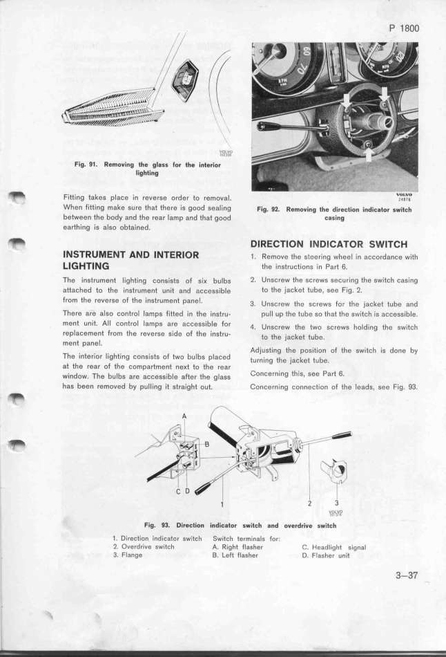
Fig. 91. Removi_g the gl8ss for th$ interior'''''''
lighting
_ Fitting takes place in reverse order to removal. _zO_'_Vi_O
When fitting make sure that there is good sealing Fjg. g_. ffemovi_g _he direGtion i_diGgtor gwjtGh
between the body and the rear lamp and that good G8sing
earthing is also obtained.
_ DIRECTlON INDICATOR SWITCH
INSTRUMENT AND INTERlOR 1. Remove the geeering wheel in accordance with
_l_HTlN_ fhe instructions in Part 6.
The 'instrument lighting congigtg of six bulbs 2_ UnsCrew the screws seCur_ng the switch casing
attached to the instrument unit and aÁcessib_e to the jacket tube, see Fig. 2_
ffom the reverSe of the _inStrUment panel 3 u th _ th _ _ t t b d
' . nSCfeW C SCreWs Or e _aC e U e an
There are also control lamps fitted in the 'instru- pull up the tube so that the switch is accessible.
ment unit. AII control lamps are acceSsible for 4. u,,crew the two screws ho_d,_ng the sw_,tÁh
replacement from the reverse side of the instru_ to the __ac_ej jube
ment panel. '
Adjusting the position of the switcf is done by
The inferior lighting consists of two bulbs placed t,rn__ng jhe __acket j,be
at the rear of the compartment ne_t to the rear '
w__ndow. The bu_bs are access,_b_e a_ter the g_age __onCerning this, See Part 6_
has been removed by pulling it straight out. Concerning connection of the leads, see Fig. 93
_ _ \
A
_
_ ___ 'Ii
_ ___i_\ __
_ _ ___,__
C _ _
j 2 3
y,QL_O,
Fig. 9_. DireGtion indiG8tor switGh and ov$rdrive switGh
1. Direction indicator switcl_ _witch terminals for_
2 Overdrive switch A. Right flash8r C. Headlight signal
3. Flange B. Left flasher D. Flasher unit 3-37
|

