 |

|
 |


Begin OCR Text:
P 1 8OO
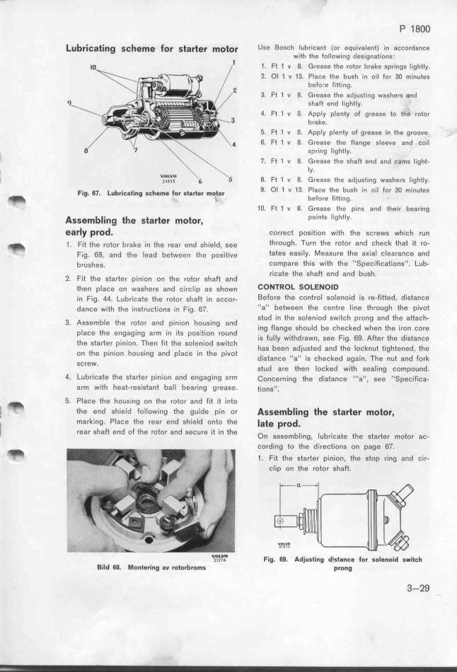
_ub_i_atin_ S_he_e _of Sta_ef _otof USe BoSCh IUbriCant (or eqUíValent) in aCCord8nCe
_ _ with the following designations.
1. Ft 1 v 8. Grease the rotor brake springs lightly.
2. Ol 1 v 13. Place the bugh in oil for 3O minutes
befo.e fitting.
3. Ft 1 v 8. Grease the adjusting washers and
__ shaft end lightly.
4. Ft 1 v a. Appty plenty of grease to the rotor
brake.
5. Ft 1 v a. AppIy plenty of grease in the groove.
6. Ft 1 v 8. Grease the flange sleeve and coil
, spring Iightly.
' 7. Ft 1 u a. G_yrease the shaft end 8nd cams light-
', 8. Ft 1 v 8. G'rease the adjusting washers lightly.
_ _ _ 9. Ol 1 v 13 PlaCe the bugh in oiI for 3O minutes
Fig. 67. Lu ricating sc eme or starter motor ' b i i
_ i e ore itting.
_ 1O. Ft 1 v 8. Grease the pins and their bearing
A b_. th t _ t points ligftly.
SSe_ in9 e S a ef _O OF,
_ eafly pfod. correct position with the screws which run
_ _ . F_,_ _he ,o_or bra_e __n _he rea, e,d sh;e_d, see through. Turn the rotor and check that it rO_
F_,g. 6g, a,d _he _ead be_wee, _he pos;_;,e tateS eaSíly. MeaSure the aKial ClearanCe and
b,ushes. Compare this with the ''SpecifiCations''_ Lub-
ricate the shaft end and bush.
2. Fit the starter pinion on the rotor shaft and
_he, p_açe o, washers and ç_;rç___p as show, _OWTROL SOLEWOlD
__, F__g. 4q. Lubr__ça_e _he ,o_o, shai_ ;, açço,. Before the Control Solenoid iS re_fitted, diStanCe
da,çe w___h _he _;ns_ruç_,o,s _, F__g. 6p. ''a'' betWeen the Centfe line throUgh the p'iVot
stud ín the soIeniod switch prong and the attacf-
3 AssembIe the rotor and pinion housing and i_ h _d b h _ d h _h .
' ing ange s ou e c ec e w en e iron core
place the engaging arm in its posítion round i __ hd F 6g Ai _h d. t
is u y wit rawn, see ig. . ter e is ance
the starter pinion Then fit the soleniod switch d d h _ k . h d _h
' has been adjuste an t e oc nut tig tene , e
on the pinion housing and place in the pi,ot d . h k d . Th d i k
istance ''a'' iS C eC e again. e nUt an or
SCreW_ t _ _h _ k _ _th __ d
s uo are en oC eu wi sea ing compoUn .
4. Lubricate the starter pinion and engaging arm _onçerning the distance '''a'', see ''Specifica-
arm with heat-resistant ball bearing grease. tio,s''.
_ 5. Place the housing on the rotor and fit it into
_ . the end shieId following the guide pin or ASSenIbling the Sta_ef _OtOf,
'i
marking. Place the rear end shield onto the late pfod.
rear shaft end of the rotor and secure it in the o b__ _ b _ t th t _ t
n assem ing, u rica e e s a er mo or aC-
_
cording to the directions on page 67.
1 . Fit the starter pinion, the stop ring and cir-
clip on the rotor shaft.
WLW F_ 6g _d_ __ d_ _ ior $o_eno_;d $w_i_c_
i_ii_ ig. . jus ing is ance
_iId 68. Montering av rotorbroms prong 3_29
|

