 |

|
 |


Begin OCR Text:
P 18OO _
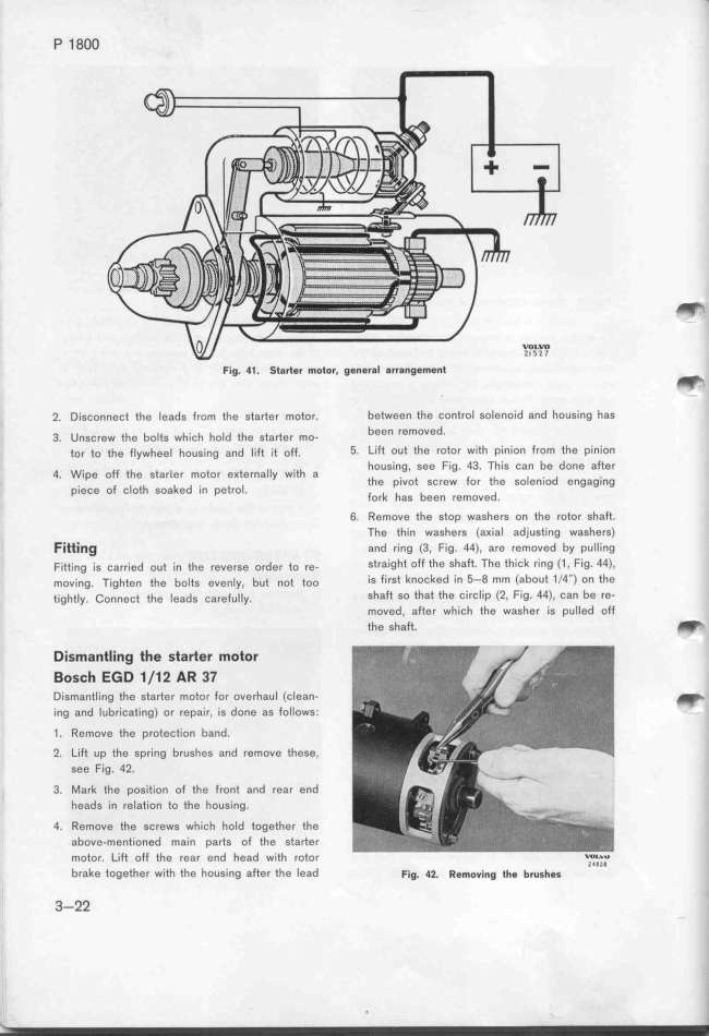
Fig. 41. St8rter motor. gener8l arrang$m$nt _
2. Disconnecf the leads from the starter motor. between the control solenoid and housing has
3. unsç,ew the boits wf_içh fo_d tfe sta_e, mo- been femoved.
tor to the flywheel housíng and lift jt off. 5_ Lìft out the rotor with pinion from the pinion
4 w.,pe off tfe sta,(e, moto, eKte,nai_y w.,tf a housing, see Fig. 43. This can be done after
' p.ieçe oe çiotf ,oa_ed .in pet,oi the pivot screw for the soleniod engaging
' tork has been removed.
6. Remove the stop washers on the rotor shaft.
The thin washers (aKial adjusting washers)
Fitti_g and ring (3, Fig. 44), are removed by puIIing
Fitting is carried out in tfe reverse o,de, to re- Straight offthe Shaft. The thick ring (1, Fig. 44),
moving. Tjgften the bolts evenly, but not too is first knocked in 5-8 mm (about 1/4'') on the
tightly. _onneçt tfe leads ça,efu_iy. Shaft so that the circlip (2, Fig. 44), can be re-
moved, after which the washer is puIIed off
the shaft. _
Disma_tli_g the starter motor
BosGh EGD 1/12 AR 37
DiSmantling the starter motor for overhaul (clean- _
ing and lubricating) or repair, is done as follows.
1. Remove the protection band.
2. Lift up the spring brushes and remove these,
see Fig. 42.
3. Mark the poS_ition of the front and rear end
heads in relation to the housing.
4. Remove the screws which hold together the
above-mention8d main parts of the starter
motor. Lift off the rear end head with rotor ___,C,_,,_
brake together with the housing after the lead F_g. 4_. ffgmov__ng __g brug_g_
3-22
|

