 |

|
 |


Begin OCR Text:
P 18OO
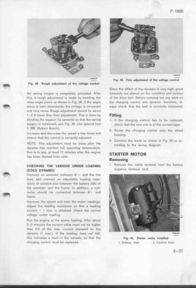
'jU,'_V_'1' Fig_ 39_ Fine 8djustment of the volt8ge EonV't Dr''o''''l'''
_ Fig. 38. Rough 8djustment of the volt8ge _ontrol Since the effect of the dynamo is very high, great
the spring tongue ís completely unloaded. After demands are placed on the condition and tension
this, a rough adjustment is made by bending the of the drive belt. Before carryinQ out any work on
relay angle piece as shown in Fig. 3_. If the angle the charging control and dynamo, therefore, al-
_ piece ìs bent downwards, the voltage is increased ways check that the belt is correctly tensioned.
and vice versa. Rough adjustment should lie about
1-2 V lower than final adjustment. This is done by FittirIg
bending the support lip upwards so that the spring _. _f _he çha,ging çon_,o_ hag _o be ,ep_açed,
tongue is tensioned_ see Fig_ 39_ Use speCial tool çheçk _ha_ _he new one ig of the ço,,gçt type.
V 395 (Robert 8osch)
' 2. SCrew the charging control onto the wheej
Increase and decrease the speed a few times and houg__ng
ensure that the control is correctly adjusted. '
3. Connect the leads as shown in Fig. 35 or ac-
NOTE. This adjustment must be done after the ço,d_ing _o the w__,__ng d_iagram
dynamo has reached full operating t8mperature, '
that is to say, at least 12 minutes after the engine __Aff_eff _o_off
has been started from cold. Removing
_HE_K___ _HE vAff_oDE u_DEff _oAD___ 1. Remove the Cable tefminal from the battery
(_o_D Dy_A_o) negative terminal StUd.
_ Connect an ammeter between B + and the live
Iead, and connect an adjustable Ioading resis-
iance of suitable size between the battery side of
the ammeter and the frame. In addition, a volt-
_ meter ghould be çonneçted between Bt and
frame.
Increase the speed and note the meter readings.
Adjust the loading resistance so that a Ioading
current -- 1 max. is obtained. Check the control
voltage under loading.
Run the engine at fhe above loading. _,fter about
2-3 minutes the current value must not be higher
l_han 2/3 of the maK. current stamped on the
dynamo (1 maK.). If the Ioading does not fall, V,o,L,v,,o
this indicates a fault in the variode, so that the Fjg. 4O. __g,_er mo_o, i_g_g__$d
charging control must be replaced. 1. _attery lead 2. _ontrol lead
3-21
|

