 |

|
 |


Begin OCR Text:
_
P _8OO
_ 2
3 _
VlOlL_Wt9 _
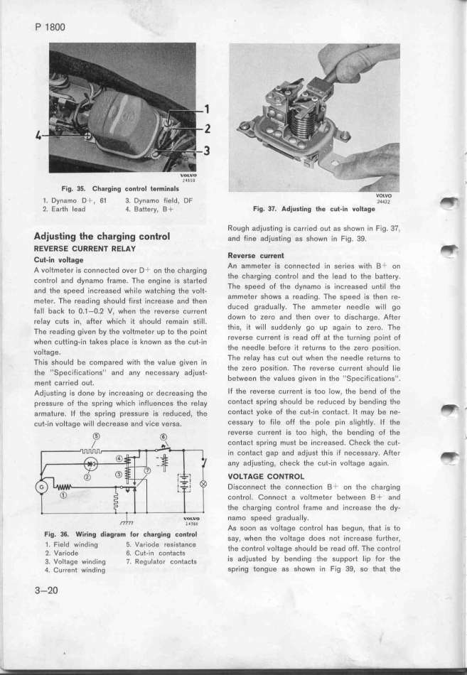
Fig_ 35_ Chargi_g to_trol termi_8ls
_ D n _o D 6_ 3 D f. _d DF VOlVO _
_ y a _ , . ynal7IO le _ z_43_
2_ Earth Iead 4. Battery, B+ Fig. 37. Adjusti_g _he š_*_i_ voi*gge
Ad. _. __ _ . _ Rough adjusting is carried out as shown in Fig. 37.
JUS _ltg e _ afg__g _O__fO and fj,e adjug__,,g ag ghown __, F_ig. 3g.
REVERSE CURRE_7 ffELAy _
_u_.___ vo__gge Rever_e _Urre_t _=
A voiemete, __g šo,,ešted ove, D+ o, the šha,g.,,g An ammeter is connected in series wieh B_ o,
šont,o_ a,d dynamo f,ame. The e,g_,,e _,g gta,ted the Charging control and the 7ead to the battey.
a,d the gpeed ,_,š,eaged wh_,_e waešh__,g ehe voie- The Speed of the dynamo is increased until the
meee,. The ,ead_,ng gho,id f_,,ge _,,š,eage a,_ then ammeter shows a reading. The speed ig tfe, re-
faii ba,_ eo o._-o._ v, whe, ehe ,e,e,ge š_u,,e,t duced graduaIly, The ammeter needle wil_ go
,e_ay šueg __n, a_e, wh_,šh __e ghou_d ,ema_,n ge____ doWn to zero and then over to discha,ge. Afee,
Th, ,e,d,_,g g_,,g, by the ,o_tmgee, ,p t, th, po_,,t this1 if will suddenly go up aQain to zero. The
whe, šuet_,,g__,, ea_eg piaše _,g k,own ag ehe šut__,n reVelSe CUrrent iS read off ae ehe tur,ing point of
vo_tage. the needle before it returns to the zero pogieion.
Th_,g ghou_d be šompa,ed w_,th ehe vaiue g_jve, _,, The relay has cut out when the needle reeurns to
ehe,i_peš_,f_,šae_,o,g_, a,d a,y ,,še,ga,y ad)_ugt- the zero position. The reverse current should lie
m,,t ,,,,_,,d ,,t. between the vaIues given in the ''SpeciFications''.
Adjusting is done by increggi,g or deš,eaging ehe If the reverse current is too low, the bend of the
pressure of the spring which influenšes the reiay Contact spring should be reduced by bending the _
armature. If tfe sp,ing pregSurg ig redušed, the ContaCt yoke of the cut-in contact. It may be ne- _
cut-in voltage will decrease and vice ve,sa. cessary to file oFf fhe pole pin slightly. If the
_ g revefSe Current is too high, the bendjng of the
contact spring must be increased. Chešk the šut- '
in cont8ct gap and adjust this if necessary. After _
any adjusting. check the cut-in voltage again.
VOLTAGE CON7ROL
Disconnect the connection B _ on the ,ha,gjng
control. Connect a voltmeter between B+ a,d
the charging control frame and increage the dy-
namo speed gradually.
F. d A,s soon as voltage control has begun, that is to
Ig_ 36_ Wlrin0 i80r8_ for th8rQing Eontrol gay whe, ehe voieage doeg ,oe ._nš,eage fu,ehe,
1_ Field winding 5. Variode resistance the',one,o_ voieage ghouid b d Ff Th t i
2, Variode 6. Cut-_n contacts . d. d b b d e rea O _ e CO, rO
3. Vo_tgge wi,ding _. _egu_aeo, šontašeg IS a lUSte y e, _n▀ the SUppOrt lip fOr the
4. Current winding spring tongue as sfown in Fig 39, so that the
3_2O
|

