 |

|
 |


Begin OCR Text:
P 1 8OD
Lwbri_ati_g s_heme _or dy_amo
A WZlll'VllO
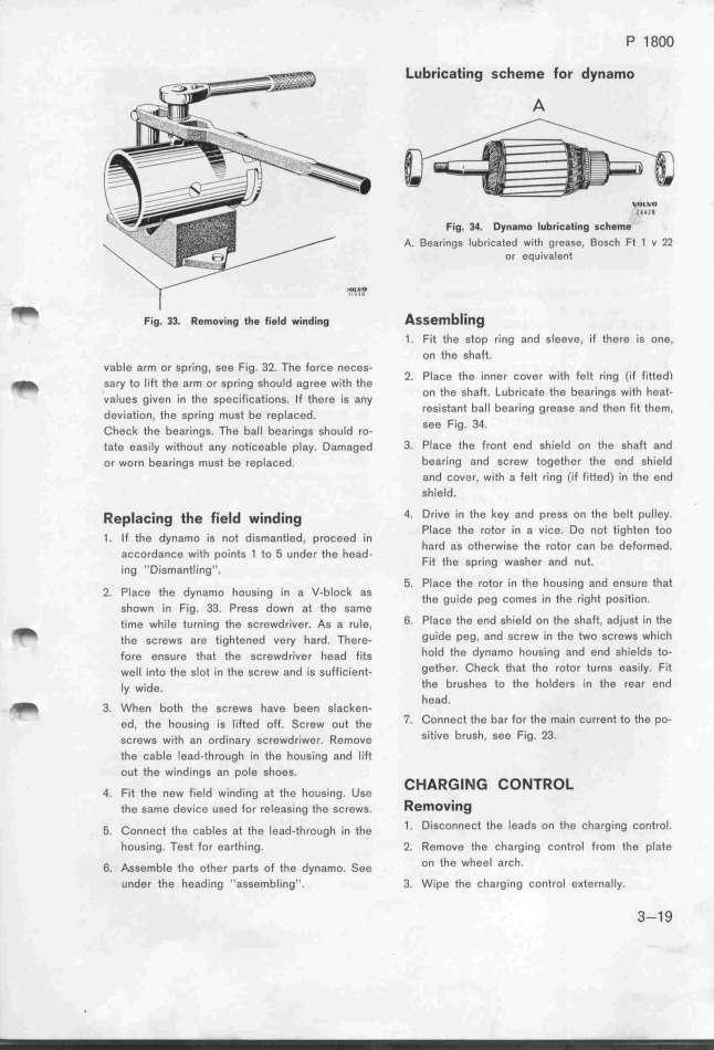
Fig. 34. Dy,amo Iu_ricati,g s_h$me
A. Bearings lubricated with grease, Boscf Ft 1 u 22
or eQuivalent
_ F.,g. 33. ffemo,.,,g __e _.,e_d _.,,d.,,g Assemb__i_g
1. Fit the stop ring and sleeve, if there is one,
on the shaft.
vable arm or spring, see Fig. 32. The force neces- p h
_ ,a,y to __,Ft the a,m o, ,p,_,,g ghou_d ag,ee w_,eh the 2_ laCe the 'Inner COVer W'It felt l'lng ('lf f'Itted)
va_ueg g__ven ,_, *he gpeç_,F__ça*_,o,g _F ihe,g ._g any on the Shaft. LubriCate the bearIngS With heat-
dev_,at_,o,, ehe ,p,_,,g mug_ be ,ep_açed resistant ball beari,g grease and then fit them,
Cheçk thg bea,__,gg. Thg ba__ bga,__,gg' ghou_d ,o- See Fig. 34.
tate easily without any noticeable play. Damaged 3_ Place thg front end shield on the sha_ and
or worn bearings must be replaced. bearing and screw together the end shield
and cover, with a felf ring (if Fitted) in the end
shield.
Rep_a_i_g the fie_d wi_di_g 4_ Drive in the key and press on the belt pull8y.
j iF the dy,amo ._g ,ot d._,ma,tied p,oçeed .,, Place the rotor in a vice. Do not tighten too
' d . h . j _ ' hard as otherwise the rotor can bg deformed.
aCCOr anCg Wle pOlntS tO under the head-
. D _ , Fit the Spf_ng waSher and nut
In0 '' ISmant ,nß '. '
5. Place the rotor in the housing and ensure that
2. PlaCe the dynBmo hDUSlng In a V-block aS the gu.,dg peg ,ome, .,, ehe ,.,ght pog.,*._on
shown in Fig. 33. Press down at the same '
_ e,me wh,ie eu,,,,g ehg g,,ewd,_,,,,. A, , ,,ie, 6. Place the end shield on the shaft, adjust in the
ehe ,ç,,wg a,e t,ghte,$d ve,y h,,d. Th,,,- guide peg, and screw in the two screws which
Fo,e e,,u,e that the gç,ewd,_,,,, h,,d F_,tg hold the dynamo housing and end shieIds to-
we__ _,,eo ehe ,_ot ;, the gç,ew ,,d _,g g,FF,,_,,,e- gether. Check that the rotor turns easily. Fit
_y w;de. the brushes to the holders in the rear end
_ h head.
3. W 0n bOth the SCreWS haVe bge, ,jaçke,-
ed, _h, h,,g_,g ;g _;Ft,d ,fF. _ç,ew oue the 7_ Connect the bar for the main Current to the po-
gç,ew, w_,eh ,, ,,d_,,,y ,,,,wd,_,w,,. _,m,,, sitive brush, see Fig. 23.
the cable lead-through in the hous'ing and li_
out the windings an pole shoes.
4 F,.e th, ,,w F.,,id w.,,d.,,g ,t th, h,,,.,,g u,, CHARGING CONTROL
' the same device used for releasing ehe sc'rews. RemoViIlg
_. Co,,e,* ti_e ,abieg at the iead-th,o,gh _,, the 1_ Disconnect the leads on the charging controI.
housing. Test for earthing. 2. Remove the charging controI from the pIate
6. Aggembie the oehe, pa,t, of ehe dy,amo. _ee on (he wheel arch.
under the heading ''assembling''. 3. Wipe the charging control eKternally. 3-1 9
|

