 |

|
 |


Begin OCR Text:
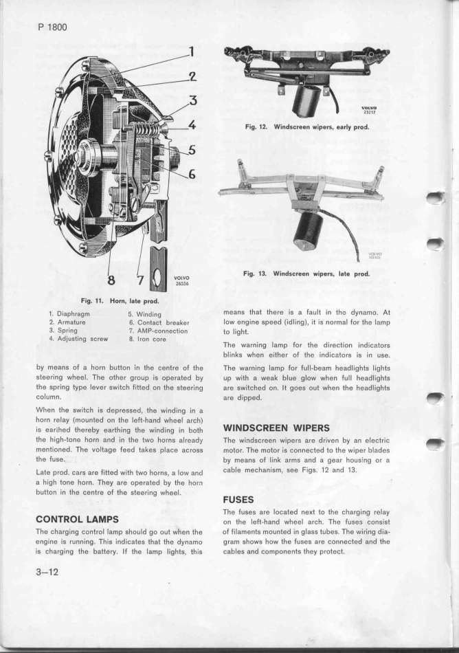
P 1 8OO Fig. 12. Windscreen wipers. $arly prod.
t
_
=-.'.''._ '.-_- _f., '
_______'- -___ -_ __--- ' _..
_-'
Fig. 13. Windscreen wipers, late prod.
Fig. 11. Horn, l8t$ prod.
_. D;ap_,,gm _. w_,,d_,,g means that there is a fault in the dynamo. At
2. Armature 6. Contact breaker low engine speed (idlìng), it is normal for the lamp
3_ Spring _i. AMP-connection to _ight.
4. Adjusting screw 8. Iron core The warning lamp for the direction indicafors
bIinks when either of the indicators is ín use.
by means of a horn button in the centre of the The warning lamp for full-beam headlights lights
steering wheeI. Tfe other group is operated by up with a weak blue glow when full headlights
the spring type lever switch fitted on the steering are switched on. It goes out when the headlights
column. are dipped. _ _
When the switch is depressed, the winding in a
horn relay (mounted on the left_hand wheel arch) .
is ear_hed thereby earthing the winding _n both WINDSCREEN WlPERS
the high-tone horn and in the two horns already The windscreen wipers are driven by an electric _
mentioned. The voltage feed takes place across motor. The motor is connected to the wiper blades
the fuse. by means of link arms and a gear hous;ng or a
' _ate p,od. cars are Fi__ed w__th two horns, a _ow and Cable meChaniSm, See FigS. 12 and 13_
a hígh tone horn. They are operated by the horn
button in the centre of the steering wheeI. FUSES
The fuses are located ne_t fo the charging relay
CONTROL LAMPS on the _e Ft-hand whee_ a,ch. The Fuse__ consjst
The charging control lamp should go out when the of filaments mounted in glass tubes. The wiring dia-
engine is running. This indicates that the dynamo gram shows how the fuses are connected and the
is charginQ the battery. If the lamp lights, this cables and components they protect.
3-12 .
|

