 |

|
 |


Begin OCR Text:
P
_ 2
' VQ.L_.O.
Early production Late production
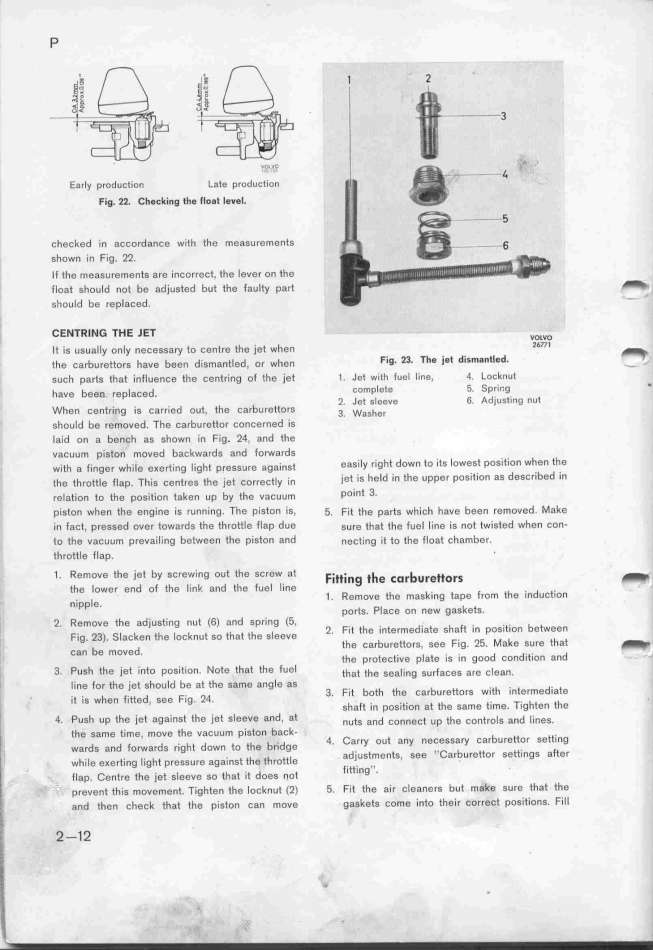
Fig. 22. Checking the _loat level.
checked ýn accordance with the measurements
shown in Fig. 22.
lf the measu,ementG are incorrect, the lever on the
fIoae shou Id no* be adjuseed but ehe fau Ity part _
should be replaced. -
CENTRING THE JET vo_vo
_* _,g ugua__y on_y nešegga,y *o šen*,e *he je* when 2677l _
*he ša,bu,g**o,g ha,g bge, d;gmane_ed, o, when Fig_ 23_ The jet dism8ntled_ - .
gušh pa_g *hg* infjuenše the cen*ring of the jet ( . Jet with _uel line, 4. Locknut
havg beg_ ,gpjašed complete 5. Sprir,g _
' 2. Jet sleeve 6. Adjusting nul
When centring is carried out, the CarburettOrS 3. w,,_,,
should be removed. The carburettor concerned is
Ia_id on a bench as shown in Fig. 24, and the
vacuum piston moved backwards and forwards
w_,eh a f_inge, wh_,_e e_e,*_i,g ___ghe p,gggu,e aga__nge ea,i_y right down to its lowest positiOn When the
eh, *h,o*eje f_,p. Th_,g ,e,i,,, *h, j_e* ,,,,,še_y _,n jet is held ýn thg upper position as described in
,,_ae_,on eo eh, pog_,*_,on *aken up by *he vašuum point 3_
piston when the engine is running. The piston is, _. Fi EUR *he p8rts which have been removed Make
in fact, pressed over towards the tl_rottle flap due sure eh8t the fuel line is not twisted when con-
to the vacuum prevailing between the piston and nešting i( to the float chamber.
throttle flap. _
1 . Remove the jet by sCrewing out the SCrew at F_______g __e _o_bu_e__o__ _
the lower end of the link and the fuel l_ine d
_ 1 Remove the masking tape from th0 In UCtion
nipp e. ' ports. P_aCe Dn neW gaSketS.
i 2. Remove the adjusting nut (6) and spring (5, d. h _ . .e. b *
F. 23) __ k *h _ k * *h EUR _h _ 2. Fit the intefme _ate S a In pOSl l On e Ween
, lg. . aC en e OC n U SO a e S eeVe k h
' b d the Carbu,ettorS, See Flg. 25. Ma e SU,0 t at _
, Can e mOYe . d d. . d
_
the p,oteCtIVe plate IS In g OO Con ItlOn an
|

