|

|
 |


Begin OCR Text:
_
P
Z
3
4
5
6
7 .
t 8
, 9 VO_vo
._ 26J72
Fig. 2O. Levers 8nd springs.
1_ Attachment for choke 5. Lever for fa_t id_i,g,
control outer casIng etc. _ --- vo_uu _
2_ Throttle flap spindle G. Lever for lowe,i,g je_ ___6__
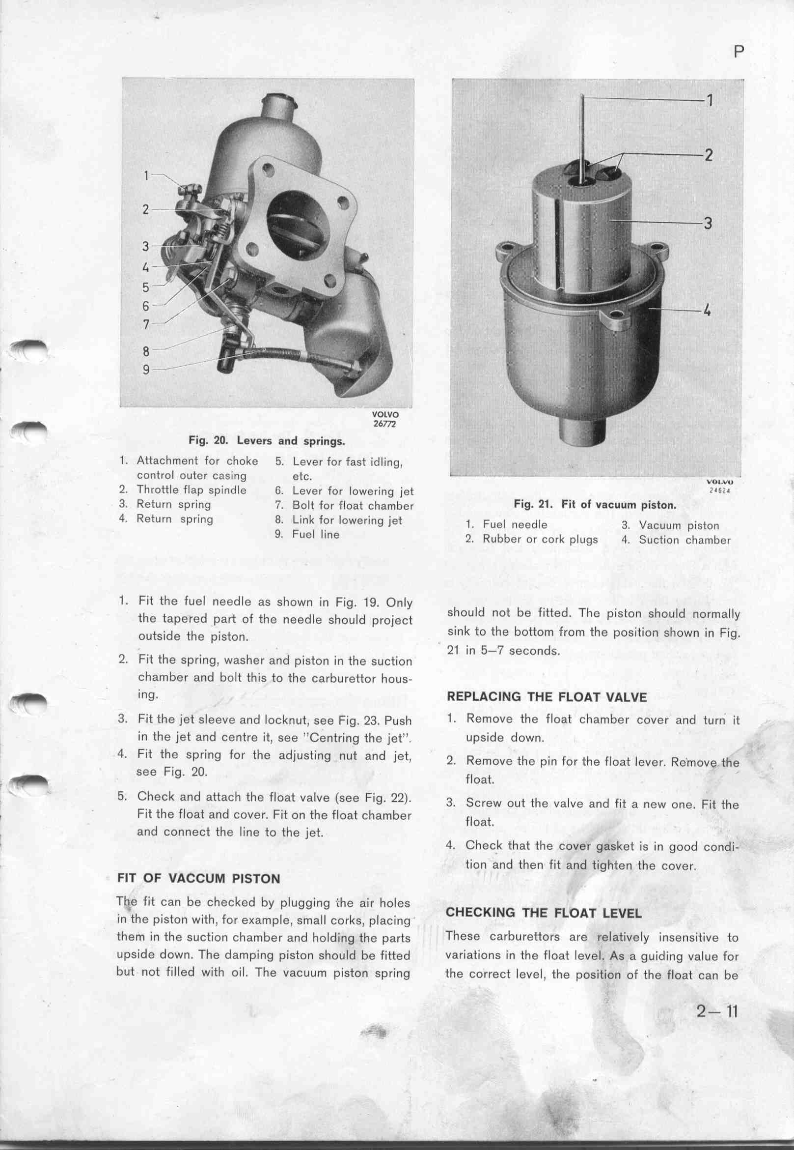
3_ Refurn spring _i. Bolt for float cha_ber Fig_ 21_ Fit ot va_uum piston.
4 Return spring 8. Link for lowering jet _. Fuei ,eed_e 3 vacuu_ p,et,,
9. Fuel line _. Rubbe, o, co,k p_ugs 4 _uct__o, c_ambe,
1 _ Fit the fuel needle as shown in Fig. 1g. O,Jy h _d
ehe tape,ed pa,e oF ehe ,eedie Shou_d p,oj.e,e S ou not be fitted. The piston should normally
oueSjde the p_,Seo,. sink to the bottom from the position shown in Fig.
2 F. h 21 in 5-7 seco,ds.
_ it t e spring, washer and piston in the suction
chamber and bolt this to the carburetto, hous-
_ ing. ffep_C___ THE FLoAT vALvE
3_ Fit the jet sleeve and locknut, see Fig. 23. _ush 1_ Remove the float chamber cover and turn it
in the jet and centre it, see ''Centring the jet'' upside down.
4_ Fit the spring for the adjusting nut and jet 2 R eh , F eh Fi e _ R h
, _ emOVe e pl, O, e Oa eVer. emOVe t e
see Fig 2O Fi
, _ ' ' Oat.
5, Check and aMach the float valve (see Fig. 22). 3. _,,,w ,,e eh, ,a_,, ,,d F.,e a ,,w ,,, F.,e th,
_ Fit the float and cover. Fit on the float çhambe, F_ '
d Oat.
. an connect the line to the jet. 4_ Check that the cover g8sket is in good condi-
tion and then fit and tighten the cover.
FIT OF VACCUM PISTo_
Th,e fit can be checked by plugging ihe air holes CHeCKI__ TH
_ eh _ e _eh F i _i k i . E FLOAT LEVEL
In e pIS O, Wl , Or eKamp e, Sma Cor S, p aCIng
them in the suction chamber and holding ehe pares These carburettors are relatively insensitěve to
upside down. The damping piston should be fitted variations in the float level. As a guiding value for
but not filled with oil. The vacuum piston spring the correct level, ehe pogjtîo, oF ehe Fioae ,a, be
2- 11
= _
|