 |

|
 |


Begin OCR Text:
_______
_ _ g
P
(2) should be removed from the engine and tho- 1 . Remove the air cleaners, fuel pipes., vacuum
rougfly cleaned. If the rubber hoses are in poor hose and controls from the carburettors.
condition, they should be replaced_ 2. u,gç,ew a__ nueg whiçh ho_d ehe ça,bu,eeeo,g
Make gu,e _hae a va_vg wieh ehe ço,,eçe de,igna- to the intake manifold.
tion (CV-584) is fitted. An incorrect valve can 3. Pull both the carburettors off at the same fime
cause impaired ventilation or oil leakage. from the intake manifold. Cover the induction
ports with masking tape.
Fue_ _y__e_ D_sMANTL_NG THE cARBuREnoRs
_o_bu_e__o_g 1 . Remove the damping piston and SUCtion Cham_
ber complete with piston.
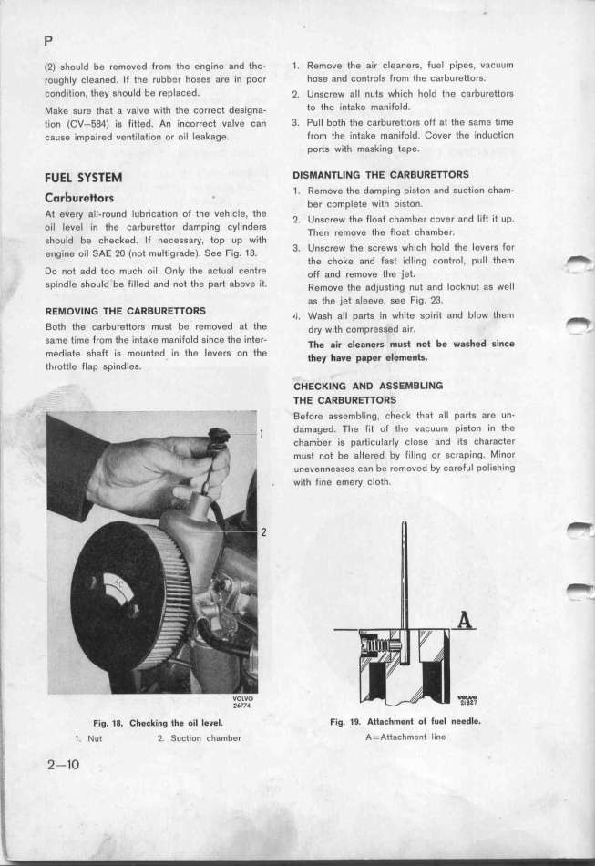
At evey aIl-round tubrication of the vehicle, the 2 ungç,ew ehe __oae çhambe, ,o,e, a,d _._e .,e up
oil level in the carburettor damping cylinders ' The, ,emove ehe iio,e çhambe, ' '
should be checked. If necessary, top up with d '
engine oi_ _AE 2o (,oe mu_e,_g,ade). _ee F__g. _g. 3_ UnSCreW the SCreWS Wh'iCh hOl the leVefS fOr
the choke and fast idling control, pull them _
Do not add too much oil. Only the actual centre o_i a,d ,emove _he j_ee. _
spindle should be filled and not the p8rf above it. _emove ehe ad)_uge_,,g ,,e and ioçk,ue ag we__
as the jet sleeve, see Fig. 23.
REMOVING THE CARBUREnORS ,_ wagh a__ pa,eg ._n wh._ee gp._,.,e and b_ow ehem
Both the carburettors must be removed at the _ dy w_,eh ,,mp,,,,,d ,_,,. _
same time from the intake manifold since the inter- T_e g.__ __e$_e_g _uge _o_ be wgg_ed g.___e
mediate shaft is mounted in the levers on the e_ey _ave pgpe_ e_e_g_eg
throttle flap spindles. '
CHECKING AND ASSEMBLING
7HE CARBURETTORS
Before assembling, check that all parts are un-
_ damaged. The fit of the vacuum piston in the
_, chamDer is p8rticularIy close and its character
' must not be altered by filing or scraping. Minor
unevennesses can be removed by careful polishing
' . with fine emery cloth.
_
_
'I, _
I_ voivo _
_
____ 2lB21
Fig. 18. Cfecking tfe oil Ievel. Fig. 19. Att8chment of fuel needle.
'_
1. Nut 2. Suction cha_bgr A= Attachment line
_
,' 2-1O
|

