 |

|
 |


Begin OCR Text:
__
P
.
1 z 3 _
1 2 3
_ . , _= _
g 8 j 6 5 voLVo _ I _
z676_ _3 1z 1_ _O g 8 7 6 5 VO_Vo
2_7_ _
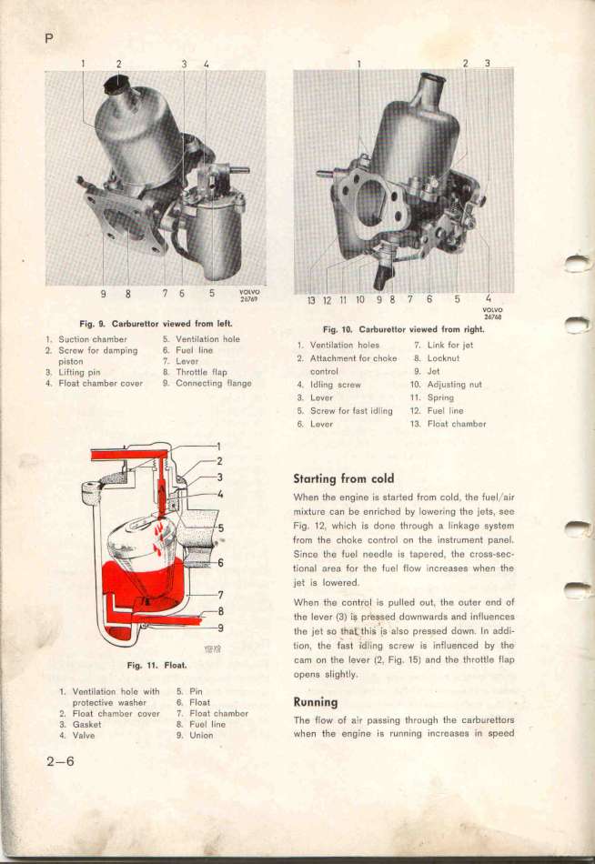
Fig. $. Carburetto_ vie_ed from left, F. o C _ . d _ . __
l0. _ . ar Ur0ttOf VieWe rOm rI0 _ _ =
1 Suçtjon cfambef 5 Ventílation hole F
' 1 Ventilation holeS 7. L_nk or jet
2. SCfew fof da_pIng 6. FUe_ lln0 _
p__s_o_ p. _eve_ 2 Attaçhment for çhoke 8 Locknut
3. _jf_ing pin 8. Throttle flap control 9_ Jet
4. Float chamber couer _ ConneCting flange 4. _dling sçrew 1O. Adjusting nuf
3. Lever 1 1. Spr_ng
, 5. Screw for fast idling 1_. F_Iel line
'_, 6. Lever 13. Float chamber
''''Ii
. __o,_;,g _,o_ _o_d
l
l, When the engine is started from cold, the fuel 'air
mi_ture can be enriched by lowering the jets, see
Fig. 12, which is done through a linkage system _
' trom the choke control on ffe instrument panel. _
i _ince the fuel needle is tapered, the cross-sec-
Ij tional area for the fuel flow increases when the
.. jet is lowered _
' When the control is pulled out, the outer end of
!_ the lever (3) is pressed downwards and influences
_, the )et so tha_thii is also pressed down. In addi-
,
? tion. the fast idIing screw is infIuenced by the
|

