 |

|
 |


Begin OCR Text:
P
1 2 3 _ 5 6 7 8 9 1O 11 12 13
_ '
_
' z6 25 2_ 23 22 21 2D 19 18 17 16 15 1_'''_'_'
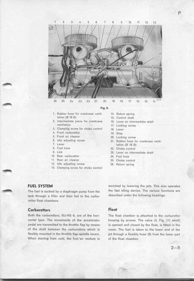
F~g. a.
1. Rubber hose for crankcase venti- 14. Return spring
Iation (B 18 B) 15. Control shaft
2. Intermediate piece for crankc8se 16. Lever on intermedi8te shaft
v8ntilation 17. Loškjng gc,ew
3. CIamping GCrew for choke controI 1g. Lgve,
4. Front carburetfor 1g. __op
5. Front air Cleaner 2O. Lockjng $š,gw
6_ IdIe adjusting screw 21. Rubbe, hoge fo, š,ankšage ven_i-
7. Lever lation (8 18 B)
8. Fuel hose 22. Choke control
9. tink 23. Levgr on inte,medi8te ghaft
1O. Re8r carburettor 24. Fuel hose
11. Rear air cleaner 25. Choke cont,ol '
12. Idle adjusting screw 26. Return spring
_ 13. CIamping screw for choke control
FUE_ _y__E_ enriched by lowering the jets. This aIso operates
_ Th, f,,_ _,, ,,,_,d by , d_,,ph,,gm p,mp f,,m _h, the fast idling device_ The uarious functionS are
_ _an_ th,ough a f_,_te, and _hgn fed to the ša,bu_ deScribed under the following headingS.
rettor float chambers.
______e_o__ Floot
Both the carburgttors, SU-HS 6, are of th, hor'i- The float chamber is attached to the carbureftor
zontal type. The mov,ments of the accelerator housing by screws. The vaIve (4, Fig. _1) which
pedal are transmitted to the throttle fl8p by means is opened and closed by the float, is fitted in the
of the shaft between the carbu,gftors which is cover. The fueI 'is taken to the lower end of the
fleKibly mounted in the throttle flap spindle levers. jet through a fleKible hose (8) from the lower part
When starting from cold. the fuel/a'ir mi Kture is of the float chamber. 2-5
|

