 |

|
 |


Begin OCR Text:
__
P
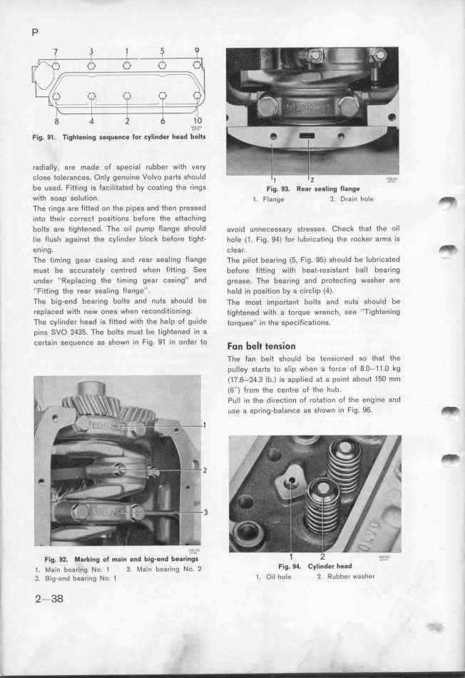
Fig. 91. Tightening sequence for cylinder head b''''_''l'ts
radially, are made of special rubber with very
close tolerances. Only genuine Volvo parts should
be used. Fitting is facilitated by coating the rings Fig. g_. _eg_ seg_ing __gng$
with soap solution_ _. F_a,ge _ Drain hole _
The rings are fitted on the pipes and then pressed
into their correct positions before the attaching
bolts are tightened. The oil pump flange shoutd avoid unnecessay stresses. Check that the oil
lie flush against the cylinder block before tight- hole (1, Fig. 9Q) for lubricating fhe rocker arms is
ening. clear. _
The timing gear casing and rear sealing flange The pilot bearing (5, Fig. 95) should be lubrícated
must be accurately centred when fitting See before fitting with heat-resistant ball bearing
under ''Replacing the timing gear casing'' and grease. The bearing and protecting washer are
''Fitting the rear sealing flange''. held in position by a circlip (4).
The big-end bearing bolts and nuts should be The mogt impo_ant bo_tg and nuts shouId be
replaced with new oneS When reConditioning_ tightened with a torque wrench, see ''Tightening
The cylinder head is fitted witf the help of guide torques_, in the gpecifjcations.
pins SVO 2435. The bolts must be tightened in a
certain sequence as shown in Fig. 91 in order to Fo_ be__ _e____o_
The fan belt should be tensioned so that the
pulley starts to slip when a force of 8.O-11.O kg
'_ (17.6-24.3 Ib.) is applied at a point about 15O mm
(6'') from the centre of the hub.
Pull in the direction of rotation of the engine and
_ use a spring-balance as shown in F_g. 96. _
_
_
_i 2
3
Fig. g_. _gr_ing o_ _a__ gnd big.end beg__n'?__g' 1 2 _;_;.n
_. _a_,, bea___,g _o. _ 3. _a_,, bear_ing _o. _ Fig_ 94_ Cylinder he8d
_, 2. _ig.e,d beari,g _o. 1 1. Oil hole 2. Rubber washer
, 2-38
|

