 |
|
 |


Begin OCR Text:
P p ihat the lever comes in the correct position
_ above its cam.
l 1
1 O D_smo_____ng _ype __
l ,
9
g _ _ ,_ 1 Make _ine-Up markS On the Upper pali and
I _ i _epa aie ihe uppe, pa_ _,om ihe
p I(_ ___ rF OWe, par . r
i _
6 OWe, paft_
_ 2. Remove one circlíp (1 53 from the lever pin <1 6).
g_ _ Press out the pin. Pull out the lever and spríng
4 _ (1 4) and (1 2).
3 .d
3. Remove the d_aph ragm (5) W Iih Spflng, gUl e
Z _2 (3) d bb _ ij) if b
_ __ an rU er Sea . e Sprlng Can e re-
_/_' _13 moved afier the rubber seal has been pulled
1
-14 up ove, ife ,y_o, wa,he,.
I5 q. u,gç,ew ife gç,ew o, ife u,de,gjde of tfe _,
, _ 16 ,ppe, pa,t, ,emove ihe eiop a,m (6) a,d gp,_,g _
? ''' ' valve (7>. The inlet valve cannot be removed.
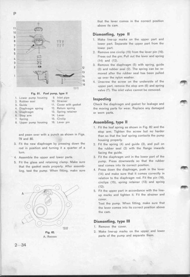
Fig. 81. Fuel p_mp, type Il
1 . tower pump housing 9 Inlet pipe lnspe_t_ing
2 Rubber sea_ 1 O. Strainer _
3. _,,de _ _ . Coue, wiif gagkei Check the d iaph ragm and gasket for leakage and
4. Diaphragm spring 1 2 Return spring ife mověng parts for wear. Replace any damaged
5. Diaphragm 1 3. Spring retainer o, wo,, pa_g.
6. Stop arm 1 O. Lever
7. Spring 1 5. Circlip b_ _l
8. upper pump housing 1 6 Lever pin Assem ing, type
1 . Fit the leaf spring as shown in Fig. 82 and the
stop arm. Tighten the screw but no harder
and peen over with a punch as shown in FigS, tfa, go ihai ihe _ga_ ,p,_,,g ço,iaçi, tfe pump
79 and 8O. h,,,,_,g p,,p,,_y.
3. Fit the new diaphragm bY Pressing down the j. Fii the spring (4) and guide (3), and pull on
rod in position and tu rning _t a quarter of a ihe ,ubbe, geal <2) with the flange inwards
turn. facing the guide.
4. Ageemb_e ife uppe, and _ower pa,iS. 3. Fit the diaphragm unit in the lower part of the
5. F_;t ihe g_a,g a,d ,eia_,,__,g ç_amp. _ake gu ,e µump. P,eg, downwards so that the rubber
ihai ihe gagkei gea_g p,ope,_y. Afie, aSgemb. Seal ComeS into itS Corr0Ct pOSit_ On_ _
__,,g, iegi the pump. whe, f_,ii_, ,g , makD_ gu,e 4. P,eSs down the diaphragm. push in the lever
(1 4) and make sure that it comes correctly in
relation to the diaphragm rod. Fit the pin C1 6),
circl ips (1 5) , spring retainer (1 3) and spring
_ -- _ , ) _ (1 j). _
l _)_/ g,,__j__ \ _ 5. Fit the upper part in accordance
with the line-
A -- _-_
'/ __- 3 _(_ _ _ / ,p m,,k, ,,d i_,ghi,, ,i. F;t tfe gi,a,,e, a,d
Il _/ ,_ _ /''_ ) ', ' _ COVer_
__/ , _, / __ \ ._ _ '__ i_ _ __ , ie,i ihe pump. When fitting, make sure that
' i __(
f_\)_ i ,1 , , __ ihe _ever comes ěn_o its correct position above
), , _'___\__ //, I/J ///,,) /)
' the Cam.
_y _b
_ _ 'i , __,
__ __ _--_'__ / /- i i ' Dismontling, type l l l
' - _ _ - _ _ - ?o,,,,v.,o, 1 . Remove the cover.
F_,g. g_. ' j. _ake _ _ne-uF marks on the upper and lowef
,. A. R,,,,, parts of the pump and separate them_
_ 2 - 34
|

