 |

|
 |


Begin OCR Text:
_
___
P
1 2
_I,
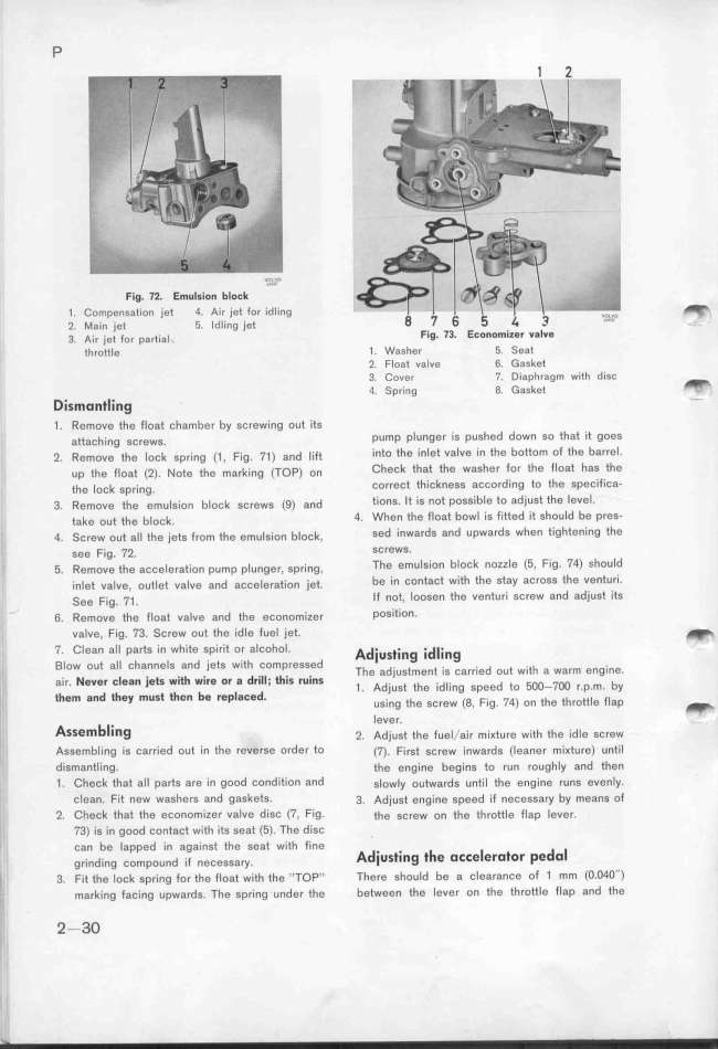
Fig. 71. EmuIsion _loCk '_''_''''
1. Compensation iet 4. Air jet for 'idling _
2. Main jet 5. Idling jet
3. A__, j_ei _o, pg__,gi Fig_ 73_ EConomi__F VaIVe
eh,oeeie 1 . WaSher 5. Se8t
2. Float value 6. Gasket
3. Cover 7. Diaphragm with disc _
O. Spring 8. G8sket
Dismontling -
1 . _emove the float chamber by screwing out its
geeacf__,g ,ç,ewg. pump plung8r is pushed down So that _it goeS
_. _emove efg _ock gp,__,g (_ , F__g. 7_ ) a,d __,fe into the inlet valve in the boMom of the barrel_
up ehg f_oai (_). _oee ife ma,k__,g (Top) o, Check that the waSher for the float has the
ife _oçk gp,_,,g. correct thickness according to the specifica-
3. _emove efg emu_g_,o, b_ock gc,ewg (g) a,d tions. It is not possible to adjust the leVel_
eake oue ihe b_ock. 4. When the float bowl is fitted it should be pres-
4. Sc,ew oue a__ efe j_ei, f,om ehg emu_g__o, b_ock, sed inwards 8nd upwards when tightening the
l_ gee F__g. 7_. SCreWS.
'i _. _emove efe açce_e,ai__o, pump p_u,ge,, gp,_,,g, Tfe emulsion block nozzle (5, Fig, 74) __hould
_,,_ee va_ve, oue_ee va_ve a,d açce_e,ae_,o, jee. be in Contact with tfe stay aCross the VentUr__
See F__g. 7_ . If not, loosen the venturi screw and adjust its
- 6. _emove ife f_oai va_ve a,d ehe eco,omize, pOSitiO,_
valve, Fig. 73. Screw out the idle fuel jet. _
7. Clean all parts in white spirit or aICohol. Ad.iust_ing ._d__ing
_low out atl channels and jets with compreseed Tf d. i e . . d i .ef e,g_,,g
_ . _ _ . _ __f . d ___ _f_ , e a JUS men IS Carrle OU Wl a Warm _
_ air. $Ver _ ean _e S Wj WiFe OF 8 Fj j iS FUjnS _ Adj.uge ehe _,d__,,g ,peed eo 5oo-7oo , p m by
i_ them and they must tfen _e r$pla_ed, ' ,g.,,g ehe gç,ew ig F.,g 74) o, efe if,öee_e 'i_ap _
_
1 _ 1 '
_ A __. eVer.
_ ssem ing _. Adjusi tfe fue_/air mi Keure wiif efe idIe sc,ew
__ Assembling is carried out in the reverse order to (7). First screw inwards (leaner miKture) until
i i dismantling_ the eng'ine begins to run roughly and then
' 1 . Check that all parts are in good condition and g_owly outwards untìl the engine runs evenly.
clean. Fit new washers and gaskets. 3. Adjust engine spe$d if necessary by means of
,_ 2. Check that the economizer v8lve disc (7, Fig_ efe screw on the throttle flap lever.
,'_, 73) is in good contact with its seat (5). The disc
l can be lapped _in againse ihe seat wieh fine d. . _ _ d _
g,_,,d_,,g ,,mp,,,d _,i ,,,,,,,,y. A iUSting t e otte efotOf _e O
_' 3. Fie ife _ock gp,ing for ehe floai wieh ife ,ITOp,, Tfere should be a clearance of 1 mm (O_O4O'')
I___ ma,ki,g faci,g upwa,dg. Tfe gp,i,g under ihe betwe8n the lever on the throttle flap and the
.'I._ _ -3o
|

