 |

|
 |


Begin OCR Text:
_
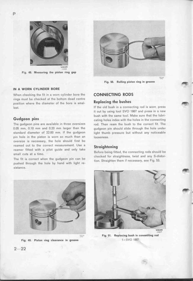
P Fig. 48. Measuring the piston'''r_i'ng gap - -
Fig. 5O. Rolling piston ring in groove ''''''*' _ _
__ A WoR_ CYLl_DEff BORE
When checking the fit in a worn cylinder bore the CONNEC7lNG RODS _
rings must be checked at the bottom dead centre R _ . _ b _
p,,_,t_,,, whe,e the d_,,m,t,, ,_ th, b,,, ;, ,ma_. eF7l O_jng t e US eS _
_e,t. If the old bush in a connecting rod is worn press V
it out by using tool SVO 1867 and press in a new
G d . bu,h with the same tool. Make sure that the lubri-
u geon _inS çat_ng ho_e, _,de_ w_th the ho_e, ,, the çonnect_ing
The gudgeon píns are available in three overSizeS rod. Then ream the bush to the correct fit The
O.O5 mm, O.1O mm and O.2O mm larger than the gudgeon pin should slide through the hole under
standard diameter of 22.OO mm. If the gudgeon _ight thumb pre,sure but without any noticeable
pin hole in the piston is worn so much than an loo,eness.
oversize is necessary, the hole should first be
reamed out to the correct meaSurement. Use a St_o_ig_te_.jng
reamer fitted with a pilot guide and only take _ _d b
__ . Before being fitted, the connecting rodS ShoU e
Sma CUtS at a tlme. d
checked for straightness. twist and any S- istor-
The fit is correct when the gudgeon pin can be . S . h th F F. _3
tlOn. tralg ten em l n0CeSSary, S0, Ig_ _
pushed through the hole by hand with light re-
sistance.
_
_ _
' ?,_o Fig. 51. Replacing bush in connectíng ro'd''''
Fig. 49. Piston ring clearanEe in groove 1--SVD 1867
2-22
|

