 |

|
 |


Begin OCR Text:
_
P
7 3 1 5 9 ffišk a,d ffe offe, _,,o go_, o.45 mm (o.o_g__)
thick. The clearance is adjusted so thaf the thj,ner
gauge can be inserted easily while the thicke, one
mUst nof enter.
When the piston in No. 1 cylinder is at top dead
centre (the compression stroke), valves _og. 1,
2, 3 and 5 (counted from the front) are adjusted,
,_._,o and with the piston in No. 4 cylinder at top dead
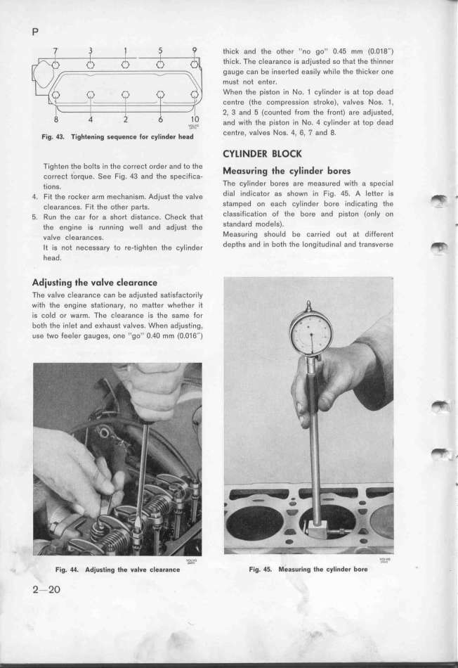
F,g. 43. __,g__e,_,,g geq,,,,, fo, ,y__,,de, _g,d Cent,e, VaIVeS NoS. 4, 6, 7 and 8.
CYLINDER BLOCK
__ighten the bolts in the correct order and foffe _eos_r._ng __ c _. d b
CO,fect tofque. See Fig. 43 and fhe gpešifiša- e Y In er OfeS
tio,g. The Cylinder bores are measured with a spešja_
4. Fit the rocke, a,m mešfan_gm. Adjugf ffe va_ve dial indicator as shown in Fig. 45. A letter is _ ,
š_earanšes. Fif the ofher pa_g. Stamped on each cylinder bore indÝšati,g fhe
5. Run the ca, fo, a sfo,f d_sfa,še. _fešk fhaf classification of the bore and piston (only on
the engine is runn_ing we__ and ad_usf thg standard models)_ _
va_ve š_earanšeg. MeaSUring should be carried ouf af differe,f
_f ig not nešegga,y to re-t,ghte, tfe šy__,,de, depths and in both the longitudinal and t,ansve,ge _
head. '
Adiusting the volve cleoronEe _
The valve clearance can be adjusted satisfaštori_y
with the engine stationary, no matter whetfer jf
is Cold or warm. The clearance is ffe game for
both the inlet and e_haust valves. When adjugfi,g,
use two feeler gauges, one ''go'' O.4O mm (O.o16'') _'
_ ,
Fig_ 44_ Adjusting tfe valve _l,aran,e ''O_'_'''O Fjg. 4_. _eggu,,,g __e ,y_,,der bore _''?'_'
2-2O
|

