 |

|
 |


Begin OCR Text:
__ _____ _ ____ _ w
_ _
g___
_ _
_ _
P
Il_
_
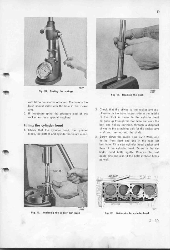
_ Fig. 39. Testing the spri_gs ''''W'' __O_'____O
_ Fig. 41. Reaming the bush
rate fit on the shaft is obtained. The hole in the
bush should inde_ with the hole in the rocker
arm. 2. Check that the oilway to the rocker arm me-
2. If necessary grind the pressure pad of the chanism on the valve tappet side in tfe middle
rocker arm in a special machine. of the block is clean. ln fhe cylinder head
oil goes up through the bolt hole, between the
Fi_i_g __e _y_i_de_ _eod boIt and hollow partition, through a diagonal
_ _h _ th t th _. d h d h _. d o_lway to the attaching boIt for the rocl(er arm
_ eC a e Cy In er ea , t e Cy In er h _ d h h
bi _ th _ t d i_ d b _ S a t an t en Up infO t e Shaft.
OC , e pIS OnS an Cy In el OleS are C ean 3. Screw down the guide píns SVO 2435, one
in the front right and one in the rear left
_ boIt hoIe. Fit a new cylinder head gasket and
'i then fit the cylinder head. Screw in the cy-
_ lind8r head bolts lightly. Remove the last
guide pins and also fit the bolts in these holes
as well.
_ WZlL_W4I 'U__,_W_
Fig_ 4O_ Repl8_ing the roeker arm bush Fig. 42. Guide pins _or _y_i_d$r hggd
2__9
|

