 |
|
 |


Begin OCR Text:
P
PV f_-_l O
_EMOVING
1 . Lift up the vehicle about 3O cm (1 2'') above
the floor and place blocks under it near the
jacking points.
2. Apply a lifting device under the engine mount-
ings. N. B. Do _ot litt o_ th$ _ater pump.
Unscrew the nuts for the front engine mounting
pads from below. Lift the engine as high as
possible without pinching anything on the
scuttle and allow it to hang on pulley blocks, a
workshop hoist, an engine lifter or sim¯lar.
3. Place a jack under the front member.
4. Clean off around the brake pipe conn8ctions
on the master cylinder. Disconnect the brake _ '
pipeg eo ehe f,one gnd on ehe mageg, cy_inde,. VzO64LV_zO
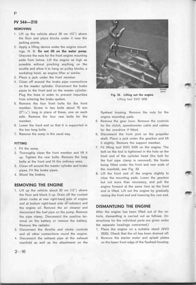
Plug the lines in order to prevent impurities Fig. 33. Liftin$ out the engin$ .
from entering the brake system. Lifting too_ _Vo 2425
5. Remove the four front bolts for the front _
member. Screw in two bolts about 75 mm
(2''/1_'') long in place of these, one on each flywhee_ housing. Remove the nues for the
side. Remove the four rear bolts for the engine mounejng pads.
member_ 5. Remove the ggar lever. Remove thg þontrols
6_ Lower the front end so that it is supported in for the clutch, speedometer þable and cables
the two long bolts_ for the overdrive if fieted.
7_ RemoVe tfe sump in the usual way. 6. Disconngct the frone joint on the propel_e,
shaft. Place a jack under the gearboK and lift
Fl7TIMG if slightly. Remove the support member.
_ . F;t the s,mp. 7. Fit lifting tool SVO 2425 on the engine. The
_. Tho,ough_y þ_ean the front mgmbe, and _i_ it bolt on the tool is tightened in the hole on the
up. Tighten ehe rea, bo_tg. Remove the _ong front end of the Cylinder head (the bolt for
bo_tg at the front and fit ehe o,d_ina,y oneg. the fuel pipe clamp is removed). the hooks
3. C_ggn off a,ound the maste, þy_inde, and b,ake being fitted under the front and rear ends of
pipeg. Fit the b,akg pipes. the manifold, see Fig. 33.
Q. B_egd the b,akes. 8. Lift the front end of the engine slightly to -_
clear the mounfing pads. Lower the gearboK
_e_ov___ _HE E____E but not more than necessay, and pull the
engine forward at the same time as the front
1 _ Lift up the vehicIe about 3O cm (1 2'') above end jg _ifted. Life oue ehe engine by g,adua__y _
the floor and block 'it up. Dr8in off the coolant ,a_g__ng the frone end and _owering the ,ea, end. _ _
(drain cocks at rear right-hand side of engine
and at bottom right-hand side of radiator) and D___A______ _HE E____e
the engine oil. Remove the air cleaner and _
disconnect the fuel pipe on the pump. Remove After the engine has been l'ifted out of the ve-
the pipe clamp. Disconnect the positive ter- hicle, dismantling is carried out as follows. (ln-
minal on the battey or remove the battery. structions for the individual parts are given under
Remove the radiator. the separate headings concerned.)
3. Disconnect the throttle and choke controls 1 . Place the engine on a suitable stand (SVO
and all other connections round the eng_ine. 252O). Cfeck that the oil has been drained off.
4. Disconnect the eKhaust pipe at the eKhaust 2. Remove the starter motor and splash pl Btes
manifold as well 8s the attachment on the on the lower front edge of the flywhe,el housing.
2-16 '
|

