 |

|
 |


Begin OCR Text:
P
components as described in points 4-8 in the
previous seCtion.
VO_Ve gf'IlId'l_g o_d de_Ofbo_'l_'l_o
1. Drain off the coolant from the radiaVtor an_
cyIinder block. (Two cocks.)
2. Dismantle the throttle control. Disconnect thp
choke control.
3. Remove the air cleaner and carburettor.
4. Disconnect the eKhaust pipe at the eKhaust
manifold and disconnešt the hoseg to the
radiator aS well as other connections to _he
cylinder he8d.
5. Remove the rocker casing, rocker arm shaft
and pUSh rOdS. _ I
6. R0moVe the Cylinder l_ead bolts and dis-
_- '
___'__ connect the water pipe as well at the 8ttach-
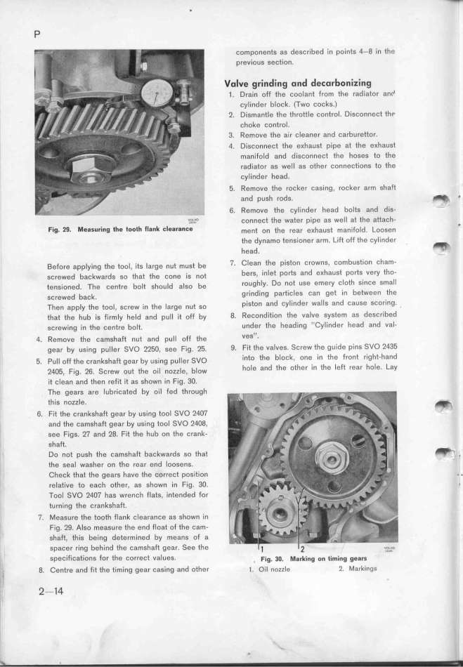
Fig. _9_ _e8SU_i_g t_e too__ f_g_k _l$g_g__e ment on t_e rear e__aust man_i_o__. _ oogen _
the dynamo_ tensioner_arm. Lift off' th'Ue c_ylinder _
head.
_efore app_y_ing tfe too_, its _arge nut mugt be 7, Clean the piSton crowns, combustion cham-
gcrewed backwards go tfat the šone js not berS, inlet portS and eKhaUSt portS vefy tho_
tengioned. The šentre bo_t sfou_d a_so be rOUghly, Do not use emey cloth since small
gcrewed bašk. grinding partiCleS Can get in betWeen the
Then app_y tfe tool, 6crew jn tfe _arge nut go piStOn and Cylinder walIS and CaUSe SCoring. .
that the hub iS firmly held and pull it off by 8. Recondition the valve syStem as described
screwing in the centre bolt. under the heading ''Cylinder head and val-
4. Remove the camgfaft nut and pu_l off the veS''_
gear by uSing puller SVO 225O, see Fig. 25. 9. Fit the valves. SCrew the guide pins SVO 2435
5. pull off the crankghaft gear by ueing pul_gr Svo intO the bIoCk. one in the ffont right-hand
2qO5, Fig. 26. Screw out the oil nozzle, blow hOle and the Oth0r in the left rear hole. Lay
it Clean and then refit it as shown in Fig. 3O.
The ge8rs are lubricated by oil fed tfroUgh
this nozzle. _-
6. Fit the crankshaft gear by using tool SVO 24O7
and the camshaft gear by using tool SVO 24O8,
S8e Figs. 27 and 28. Fit the hub on the crank-
Sha_.
Do not push the camGhaft backwards so that __ ,
the seal washer on the rear end loosens.
'
Check that the gears have the correct position . .
fel8tive to each other, as Shown in Fig. 3O. ,
ToOl SVO 24O7 haS wfenCh flats, intended for
turning the crankshaft.
7. Measure the tooth fIank C_garanše as ghown jn
Fig. 29. Also measure the end Float of the šam-
shaft, this being determined by means of a
spacer ring behind the camshaft gear. See the
SpeCifjCations for the correct va_ues. , F_ig. 3o. _g_k_ing o_ t_i__i_g gegK
_ 8_ Centre and fit the timing gear CaSing and other _. oil _ozz_e _. _arkingg
_ 2-14
|

