 |

|
 |


Begin OCR Text:
P
l 2 3 _ 5 6 p
_
' l l5 l_ l3 l2l1 lo g vo_vo g
F. _ G b '_C FI0_ 8_ G8_Ut$MOr
_ ig_ _ ar ur$ttof _. Eço,D___ze, vaive g. __,,_
_ 1_ L8Vgr with guid8 9. Idl8 fueI adju_ting _. __oke __ap g. Aiiaç_me,e
2_ Lever for choke flap screw 3. _p,i,g _o. _d_e gdjuge_,,g g_,ow
3_ Rear lever 1O. Vacuum connection q. Leve, Fo, ç_o_e __. _o,,gcio,
4. Spring 11. Stop _. Levg, w_e_ g,;de __. Loç_ __ç,ew _o,
5_ Front lever 12. AMachment for chokc 6. _gpid id_g adjuge_,g ve,e,,;
6_ Plunger rod contrDl gc,ew _3. Ca,bu,g_o, _oug_i,g
7_ Washer for adjust- 13. Idle adj_sting screw p. Rgpid ,d__,g çam _4. Fioai ç_ambe, _
ment of stroke length 14. Link
_. Fuel inlet 15. Connection for
throttle controf . (p h f_ d
Spring ) on t e ap Spin le so that it closes,
thereby resulting in a higher degree _of vacuum
and consequently a higher rate of fuel flow. When
1_ FLOA7 SYSTEM ih _ h i e d d ih d f
e en9lne aS S af e an e egfee o vacuum
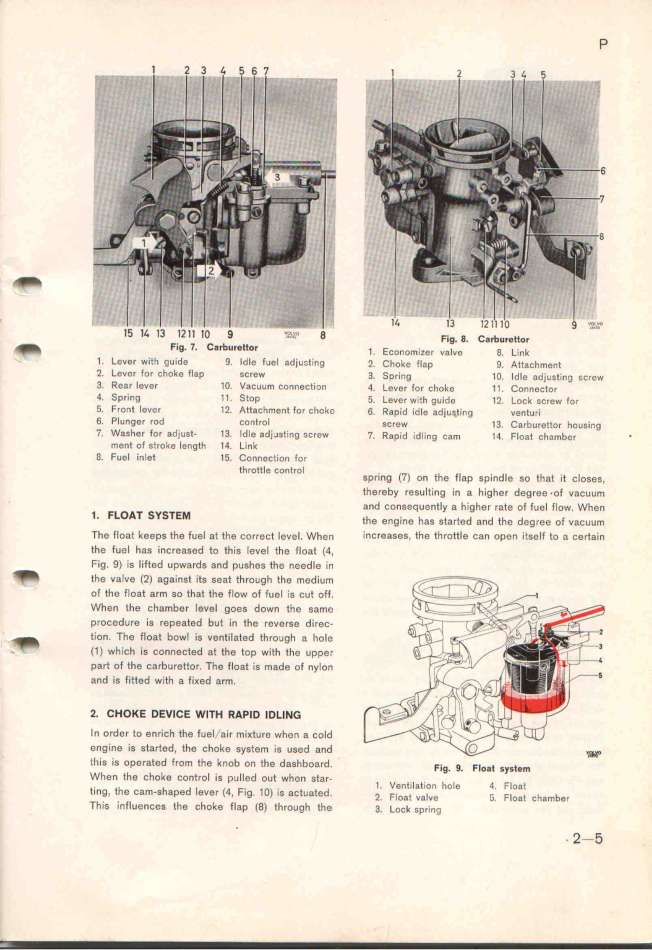
The float keeps the fuel at the cDrrect level. When increases, the throttle can Dpen itselt to a cert8in
the fuel has increased to this level th8 float (4,
_ Fig. 9) is lift8d upwards and pushes the needle in
the vafve (2) ag8inst its seat through the medium
of the Float arm so that the fIow of fuel is cut off.
When the chamb8r l8vel goes down the same
procedure is repeated but ìn the revers8 direc-
_ tion. The float bowl is ventilated through a ho_e
__ (1) which is connected at the top wifh the upper
part of the carbur8ttor. The float is made of nylon
and is fitt8d with 8 fi_ed arm.
2. CHOKE DEVICE WlTH RAp_D _DLING
In order to enrich tfe tuel/air mi_ture whe, g ço_d
engine ie Started. the choke system is u6ed and
tl_is is operated from the knob on thg dgghboard. F.,g g F_o,i __,i,_
When the choke control is pulled out when siar- ' '
e. ih h d _ 1. Ventilat1on hole 4 F_oat
lng, e Cam-S ape eVer (4, Fig. 1O) iS aCtuated _ F_ e i _' F_ h b
Th . fi ' _ Oa UBve _. Oat C am e,
is in uences the choke flap (8) through the 3. Loç_ ,p,_,,g _ 2-5
|

