 |

|
 |


Begin OCR Text:
P
, Oil _ilter
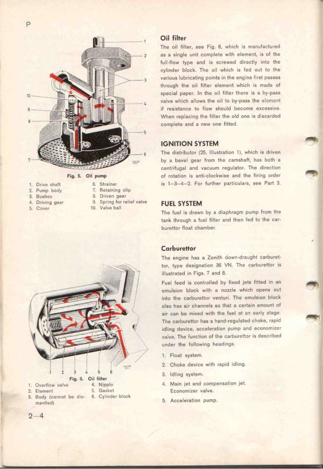
The oil filter, see Fig. 6, which is manufactured
_ as a single unit complete with element. is of tfe
fuIl-flow type and is screwed directly into the
cylinder block. The oil whieh is fed out to the
3 various lubricating points in the engine first passes
through the oil filter element which is made of
_o SpeCial paper. In the oil fitter there iS a by-paSs
4 vafve which allows the oil to by-pass the e!cment
9 if resistance to flow should become eKcessive.
When replacing the filtar the old one is disc8rded
B Complete 8nd a new one fltted.
5 ______o_ _y__E_ _
6 Tfe distributor (25, Illustratýon 1), which is driven
7 by a bgve_ gear from the šamghaft. fag botf a
centrifugal and vacuum regulator. The direction _
Fig_ 5_ Oil pump of rotation is anti-clockwise and the firing order '_
1. Drive _ph8ft 6. Strainer is 1-3-4-2. For further particulars, see Part 3_
2. Pump body 7. Retaining clip
3. Bushes l3. Driven gear
4 Driving gear _. Spring for relief valve FuE_ _y__E_
'_ Cover 1O. Valve bafl The fuel is drawn by a diaphragm pump from the
t8nk through 8 fuel filter and then fed to the car-
burettor float chamber.
_orb_rettor '
The engine has a lenith down-draught carburet-
__ _._ ___ tor, type designation 36 VN. The carburettor is
illustrated in Figs. 7 and 8.
Fuel feed is controlled by fiKed jets fitted in an _
gmulsion block with a nozzle whých opens out _
into the carburettor venturi. __he emulsion block _
; a_go hag ajr šfanne_g so that a c8rtain amount of
air can be miKed with the fuel at an early __tage_ _
The carburettor has a hand-regulated choke. rapid
idljng device, acceleration pump and economIZer
vglve. The function of the carburettor iS described
, under the following headings.
1 . Float system.
2. Choke device with rapid idling
l 2 3 4 5 6 3 _d_.ing gygtem
Fig. _. OiI tilt$r ' '
,. Ove__low valvš 4. NippIG O. Main jet and compensation )et_
_ 2. Element '_, G8_ket Ešonomizer valvg.
3. Body (cannot be di___ 6. Cyl_nder block
_ _a_t_ed) 5. ACCeleratiOn pUmp_
2-Q
|

