 |

|
 |


Begin OCR Text:
P
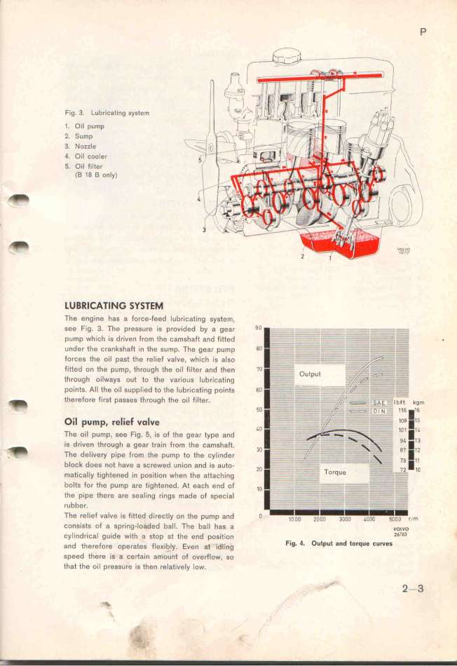
Fig. 3. Lubricating system
1. Oil pump
2_ SU_p - _
3. Nozzle __\-__j
4. Oil Cooler __/'i
5. Oil filter _
(B 18 B only) l__ i ,
_ 41 l___ l_
' 3II '
t LUBRICATING SYS7EM
The engine has a force-feed lubr'icating system,
gee Fig. 3. The preggure is provjded by a gear 9O
pump which is driven from the camshaft and fitted
_
under the crankshaft in the sump. The gear pump 8O
forces the oil p8st the relief valve, which is also
fitted on the pump, through the oil filter and then 7O
through oilways out to tfe various lubricating
points. All thg oil supplied to the lubricating pointS 6O
_ th8refore first passes through the oi1 fiIter. m
fO
Oil pump. relie_ volve _O
The oil pump, see Fig. 5, is of the gear type and
is driven through a gear train from the camshaft.
_ 3O
_. The delivery pipe from the pump to the cylinder
b_ock doee not have a gcrewed union and is auto_ _O
matically tigftened in position when the aXaching
_ bolts for the pump are tightened. At each end of _D
the pipe there are sealing rings made of speciaI
rubber.
The retiet valve is fiXed directly on the pump and O j___ i___ i_ii i__ i___ r/m
cons'ists of a spring-loaded ball. The ball has a vo_vo
d _ d . h f d . . 1_783
cyIin rica gui e wit a stop at t e en position
f_ b_ d Fig. 4. Output a_d torque _urves
and therefore operates e_i =y_ . Even 8t i l'ing
speed there is a certain amount of overflow, so
that the oil pressure is then relatively low. -__ 2-3
_ 'i' .,_.,. .
|

